Mastering LED Dimming: The Ultimate Guide to Customized Lighting
What is Dimming?
AN INTRODUCTION TO DIMMING LEDs / HOW TO DIM LEDS / LED DIMMING
Dimming means reducing the output of a lamp or lighting fixture.
The output of a lamp or lighting fixture is measured in lumens (lm) and is sometimes known as its “luminous flux”. As a lamp or fixture is dimmed its lumen output decreases.
CAN LEDs BE DIMMED?
Yes, all LEDs can be dimmed, but it is not always simple. If it is practical or not to dim a particular LED lamp or lighting fixture will depend on the driver that is being used to control it. So, to answer the question “Can these specific LEDs be dimmed?” it is necessary first to understand a little about LEDs and drivers.
All LEDs need a driver, which is a piece of electronics. Its main function is to run the LEDs at the correct voltage and current, converting the mains AC supply (typically 230V, 50Hz) to, usually 12 or 24V DC. This is necessary because LEDs don’t operate on mains. LEDs work at low voltages on direct current.
In commercial lighting fixtures, such as LED panels, downlights and spotlights, the driver is usually separate from the fixture. This means that the driver is accessible to the installer so that, if the driver is the appropriate type, dimming control wires, in addition to the mains supply wires, can be connected to it.

An LED panel with its driver. The driver is separate from the panel, so it is accessible for the connection of dimming control wires if required.

In LED lamps the driver is built-in and cannot be accessed. The LEDs and driver come as a single sealed item.
An LED lamp. The driver is in the lamp base and the unit is sealed, so there is no possibility of connecting any dimming control wires.
So, to answer the very general question “Can LEDs be dimmed, and how do you do that?” one first has to determine if the driver is separate and accessible or if it is integrated with the LEDs.
DIMMING LEDS WHICH HAVE A SEPARATE DRIVER
If the driver is separate from the lighting fixture, or is accessible within it, then the best way to dim the LEDs will be by using a dimming driver. This is how most dimming is achieved in commercial and industrial installations.
Installing a common design of commercial light fitting. The LED driver – seen here to the left of the picture – is a separate item and is accessible to the installer.
If desired, the driver can be the dimming type, performing the twin functions of a driver (transforming the incoming power from 230V AC to 12-24V DC) and a dimmer.
A dimming driver performs two functions: it is both a driver and a dimmer.
As a driver it converts the mains AC supply (typically 230V, 50Hz) to 12-24V DC. This is necessary because LEDs don’t operate on mains. LEDs work at low voltages on direct current.
As a dimmer it raises and lowers the amount of electrical energy flowing out to the LEDs. There are two mains ways that a driver does this - pulse width modulation (PWM) or amplitude modulation (AM) - and these are discussed below. However, if a driver uses PWM or AM is generally of little interest to an installer or specifier. They are internal to the driver and have little or no effect on the end user and the quality of the dimmed light they will see. The more important question for the specifier and installer is how the driver is to be instructed to make the LEDs brighter or dimmer.
There are several ways to control a driver, or instruct it what to do. In each case the driver will require a continuous supply of mains power plus a control signal to tell it what to do. The most common methods of controlling a driver are as follows:
DALI (Digital Addressable Lighting Interface). DALI is the most widespread communications protocol for commercial lighting control in use today. A DALI signal is delivered to the LED driver(s) via two wires that are in addition to the wires delivering the mains supply. Many manufacturers supply LED drivers that will accept a DALI input.

This is how a DALI driver would normally be wired.
- 1-10V analogue control. This is an analogue communication protocols. Like DALI, it is delivered to the driver on two wires that are in addition to the mains wires.

This is how a 1-10V driver would normally be wired.
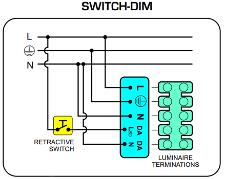
- Switch dim, touch dim, push dim. These all use one extra wire carrying an additional mains supply to a dedicated terminal on the driver. The control device is usually a retractive (non-latching) switch making/breaking the wire carrying the additional live supply; a quick push on the retractive switch will cause the driver to switch the LEDs on/off while a longer push instructs the driver to dim the LEDs up or down.

This is how a driver would be wired for switch dim, touch dim or push dim control.
- Corridor function. This is a variation on switch dim/touch dim/push dim (above). As with switch dim, an additional mains supply is connected to a dedicated terminal in the driver. However, instead of using a retractive switch as the control device, corridor function uses a latching switch, typically a motion sensor (PIR or microwave) or a time switch. This connects or disconnects the additional mains supply which indicates to the driver that is should switch the LEDs on, off or dim to a pre-set level.
- DMX (Digital Multiplex). This is a communications protocol that originated in theatre lighting but which is also widely used for other colour changing applications such as façade lighting.
- Wireless control. Several wireless technologies are available for communicating with LED drivers, including Zigbee and Bluetooth.
HOW A DIMMING DRIVER WORKS
A dimming driver has two functions:
- As a driver, it converts the 230V AC mains input to a low voltage DC output.
- As a dimmer, it reduces the amount of electrical energy flowing to the LEDs, thereby causing them to dim.


Examples of dimming drivers as would commonly be used in or alongside commercial/industrial LED light fittings. Both these units perform dual functions; they are both a driver and a dimmer.
To function as a dimmer they both have extra terminals where control wires can be connected to provide a dimming control signal.
Drivers may use either of two techniques to reduce the amount of energy flowing to the LEDs.
- Pulse width modulation (PWM)

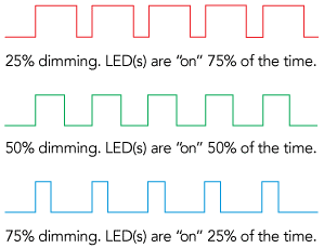
An LED driver that dims by using PWM is switching the power to the LEDs on and off. The longer the “on” pulses and the shorter the “off” pulses, the brighter the LEDs will appear to be, and vice versa. Provided this takes place at a frequency greater than about 200Hz any flickering will not be visible to the human eye and the brain will average the perceived level of brightness.
- Amplitude modulation (AM). Here the driver is simply increasing or decreasing the output current to the LEDs. The risk of flicker is eliminated, but some LEDs change colour slightly if their current is altered, especially at low levels.
Some LED driver manufacturers use a combination of PWM and AM to achieve an optimal performance.
DIMMING LED LAMPS & FIXTURES WITH SEALED-IN DRIVERS
With most LED lamps the driver is sealed inside. This is also true of many fittings designed for residential use. In both cases there is no means of delivering to the driver any sort of dimming control signal. Therefore, if dimming is required it must be done by fitting an external dimmer to the incoming mains supply to the LED lamp or sealed fixture.

A widely used type of LED lamp. The driver, which converts the incoming mains supply (230V AC) to low voltage DC, is located in the base of the lamp. If it is designed to be “dimmable”, this lamp could be dimmed with a suitable dimmer fitted on the incoming supply to the lamp.

A fire-rated downlight, popular for residential use. The driver is sealed in the housing with no provision for connecting a dimming control wire. Like a dimmable LED lamp, this could also be dimmed with a suitable dimmer fitted to the incoming supply.
This has a significant impact on the design of the driver in the lamp or fitting. An external dimmer increases and decreases the amount of electrical energy flowing into the LED lamp or sealed fitting and it usually does this by switching the supply off and on (for a variable duty cycle) at 50Hz. If the driver is to work under these conditions it has to be designed accordingly. This gives rise to the concept of a “dimmable or non-dimmable” LED lamp or driver.
A dimmable LED lamp is one which is designed to be dimmed by an external (separate) dimmer. However, even a dimmable LED lamp might not be suitable for use with all types of dimmer, so it is important to check what sort of dimmer is recommended for the LED lamp or fixture you wish to dim. The next section (below) describes the main types of dimmer that are available.
A non-dimmable LED lamp or fixture is just that. It is not designed to be dimmed at all.
WHAT TYPES OF LED DIMMER ARE THERE?
The most common LED dimmers are phase-cutting dimmers.
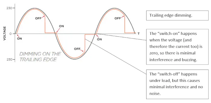
All phase-cutting dimmers work by switching the AC mains supply to the LED lamp on and off twice in every mains cycle. This has the effect of reducing the flow of electrical energy to the LED lamp or fixture, so reducing its light output.
There are two types of phase-cutting dimmers.
- Leading edge phase-cutting dimmers (also known as triac dimmers and rising edge dimmers). These work by switching the current off at the zero-crossing point (see diagram) and on again later in the same mains cycle. The amount of energy flowing to the LEDs depends on the duration of the “off” period. The longer the off period the dimmer the LEDs will appear to be.

- Trailing edge phase-cutting dimmers. These work by switching the current on at the zero crossing point (see diagram) and off later in the mains cycle. Usually this is done with an electronic component called an isolated gate bipolar transistor (IGBT). The amount of energy flowing to the LEDs depends on the duration of the “off” period. The longer the off period the dimmer the LEDs will appear to be.

Please note that we have been talking here about dimmers that operate on the mains (input) side of an LED lamp or other LED/driver sealed unit. In these applications we talk about LED lamps and LED drivers that are “dimmable” – meaning that they can be dimmed successfully with a separate (suitable) dimmer installed on their mains supply. This approach is most widely used in small and residential situations.
When dimming in a commercial environment we generally use dual-function drivers that incorporate their own dimming capability – see above “DIMMING LEDS WHICH HAVE A SEPARATE DRIVER” – and we call these “dimming” drivers.
WHAT IS THE BEST TYPE OF LED DIMMER TO USE?
To identify the best dimmer to use for a particular LED lamp or sealed LED/driver light fitting check with the manufacturer first. Ask if the item is dimmable. If it is, ask if the manufacturer has a list of their recommended dimmers. If there is no such list and they give no further guidance then follow these steps:
- Check the load on the circuit you plan to dim. To do this, add up the wattage of all the lamps/fittings on the circuit and then select a dimmer whose load range (in watts) straddles this value. A common error is to use a dimmer with a minimum load of, say 60W, when the load on the circuit you wish to dim is only 20W. This will not work well.
- Select a dimmer that is described as “trailing edge” (see above), or which advertises itself as “suitable for LEDs”. In the absence of more specific advice, a trailing edge dimmer is much more likely to work well with a dimmable LED lamp or fixture than a leading edge dimmer.
How LED Dimmers Work
By now, we should all be familiar with LED lighting as one of the most versatile and highest performing options on the scene. While it can be a great way to improve the efficiency and overall illumination power of your lighting plan, there are a few things to consider in terms of dimming capabilities. Being able to dim lights as needed is a great feature that LED solutions are catching up to, but there are still some things to keep in mind. So, how do LED dimmers work? What do you need to know before you install them? Let’s take a closer look at this topic.
How do LED dimmers work?
While many people think of dimming lights being achieved by reducing the voltage and therefore the light as well, LED solutions tend to take a different approach. With an LED, the voltage remains the same whether the solution is operated at full capacity or a dimmed capacity. The LED simply creates a dimming effect by means of either pulse width modulation or analog dimming.
With the first option, the fixture essentially creates a pulsing of light levels which are in essence flickering between high and low (or bright and dim) which are rapidly fired off in millisecond successions. The light basically cycles between on and off so rapidly it is undetectable. Since the human eye only perceives the light tone and not the flicker, it achieves a dimming appearance even though the actual light output remains the same. The second option of analog dimming relies on the actual reduction of the current flow to create the dimming effect. However, with this method, the quality of the light is diminished so it is less effective than the pulse width modulation method.
Are LED dimmers the best option?
While LED is nearly always the best option for other reasons, this type of fixture is still catching up to the dimming abilities of comparative fixtures. In terms of efficiency, LED lights are still the best option overall, but with dimming, you should keep in mind you are still basically running the light at full voltage and energy costs whereas a fluorescent dimmable usually uses a lowered voltage to achieve the dimming factor. It really depends on how often you intend to dim the lighting solution and how much this factor of energy efficiency matters to you. This is not to say that dimmable LED isn’t a great choice, but there are certain elements the industry is still looking to improve upon with this application.
Understanding LED Dimming: A Comprehensive Guide
LED dimming offers versatile control over your lighting, letting you adjust the brightness to your preference. Here’s a deeper look into the key dimming technologies available:
-
0-10V Dimming: One of the earliest forms of dimming for LED lights, 0-10V dimming operates by sending a low-voltage control signal between 0 and 10 volts. The brightness of the light is directly proportional to the voltage; a 0V signal turns the light off, while a 10V signal lights it fully. This analog system is typically found in commercial applications.
-
TRIAC (Triode for Alternating Current) Dimming: Known as leading-edge dimming, TRIAC is popular in residential settings due to its compatibility with standard wall dimmers. By cutting off a portion of the AC waveform, TRIAC dimmers reduce the voltage and thus the brightness of the light. However, not all LED drivers are compatible, so it’s essential to use dimmable LEDs designed for TRIAC controls.
-
DALI (Digital Addressable Lighting Interface) Dimming: This digital protocol enables two-way communication between the controller and lighting fixtures. Each light can be individually addressed and controlled, allowing for intricate lighting scenes and precise dimming levels. DALI is frequently used in large-scale commercial projects for its advanced control features.
-
Wireless Remote Dimming: Utilizing modern wireless protocols such as Zigbee, Bluetooth, and Wi-Fi, wireless remote dimming allows users to control their lights via a smartphone app or remote control. This method is perfect for smart homes, providing easy scheduling and integration with other smart devices.
When selecting a dimming system, consider compatibility between dimmers, drivers, and LEDs. Choosing the right method ensures smooth, flicker-free dimming and optimal performance.
Choosing the right dimming method depends on the specific needs of the project, whether it's a large commercial building or a cozy smart home. Consider compatibility between dimmers, drivers, and fixtures, and weigh the benefits of each approach to create a reliable, efficient, and visually appealing lighting environment.


Laissez un commentaire